ReadyParts4U
101474901 24-36V 275A Motor Controller for Curtis EZGO 1204-009 1204-015
101474901 24-36V 275A Motor Controller for Curtis EZGO 1204-009 1204-015
Low stock: 1 left
Couldn't load pickup availability
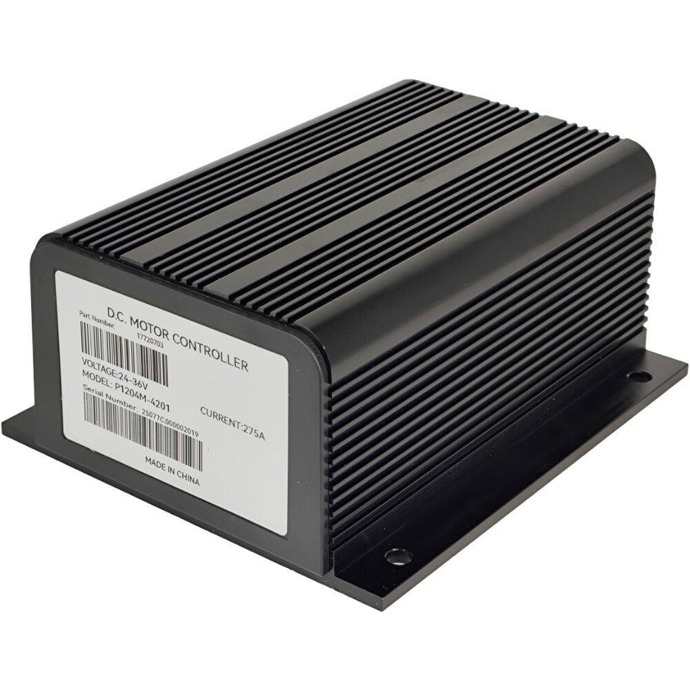
Part Number:
1204M-4201
Repalce Part Number: 1014749-01, 101474901, 20972G1, 20972-G1, 20972-G01, 27094-G01, 74244, 1204M-5302, 1204-001, 1204-004, 1204-009, 1204-015, 1204-022, 1204-034, 1204-101, 1204-102, 1204-104, 1204-127, 1204-402, 1204-404, 1204-406, 1204-408, 1204-502, 1204-506, 1204S-4403, 1204X-4201, 1204X-4401, 1204-003, 1204-005, 1204-006, 1204-011, 1204-012, 1204-017, 1204-019, 1204-020, 1204-024, 1204-025, 1204-035, 1204-036, 1204-032, CP20972-G1, 1014749-01, 101474901, 1204-027, 73055-G02, 73055G02, COLUMBIA H/D 74883-87, CUSHMAN 831722, MELEX 510154
Specification:
Voltage: 24-36V
Current: 2 min 275A, 1 Hour 125A
Throttle type: 0-5K
Application:
Compatible with Club Car 1990-1994 DS
Compatible with E-Z-GO 1989-1994 Marathon Electric Model
Features include:
1.Universal logic board supports multiple throttle types and high pedal disable (HPD) options.10.Easily programmable through the handheld programmer 1313-4331 or 1314 PC programming station.
1.Universal logic board supports multiple throttle types and high pedal disable (HPD) options.
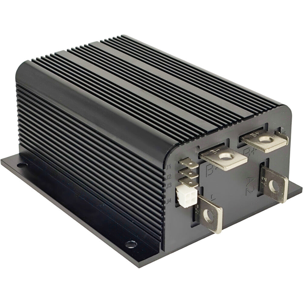
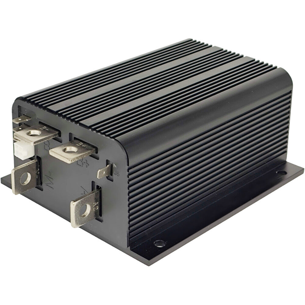
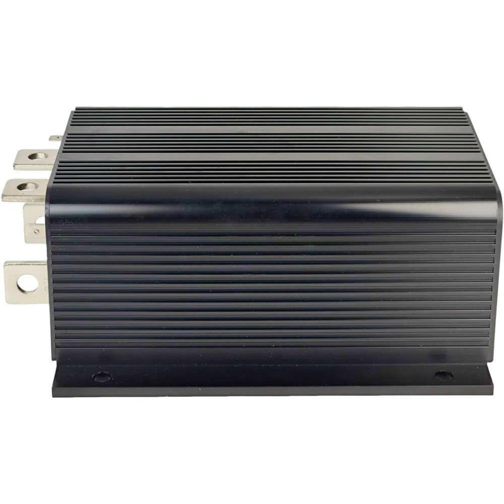
2.Protection provided by rugged anodized aluminum extruded housing.
3.Simple mounting and wiring with push-on connectors for control signals.
4.Plated solid copper buses used for all power connections.
5.Thermal protection and compensation circuit provides constant current limit over operating range and during under/over temperature cutback; no sudden loss of power under any thermal conditions.
6.Throttle fault protection circuitry disables controller if throttle wires become open.
7.HPD feature prevents controller operation if key is turned on while throttle is applied.
8.Plug braking diode internal to controller.
9.Undervoltage cutback function protects against low battery voltage, including low voltage caused by external loads.
10.Easily programmable through the handheld programmer 1313-4331 or 1314 PC programming station.
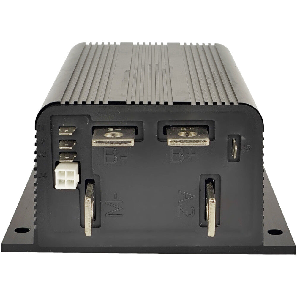
Connections:
High current connections:
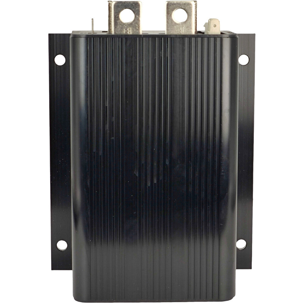
These controllers have four high-current busbars: B+, B-, A2, and M-. The busbars are tin-plated solid copper.
B+ Battery+ and motor armature. (plug diode -)
B-
A2 Motor armature and field (plug diode +).
M- Motor field (controller output). Cables used for the battery and motor connections must be heavy enough to carry the high current required. A minimum size of 25 mm2 (#4 AWG) is recommended.
Connections to the controller busbars should be made with lugs suitable for the cable used, fastened by M8 bolts and nuts. When tightening the bolts, two opposing wrenches should be used. Failure to use the double-wrench technique could cause undue strain to be placed on the internal connections, and could also result in cracked seals around the busbars.
Low current connections:
This is an upgraded controller featuring a J4 connector, designed for status LED indication or programming interfaces.
These controllers have five low-current connections: four 6.35 mm push-on terminals (J1, J2, J3, and J5), and one 4-pin connector (J4).
J1: Keyswitch.
J2: Wire 1 of 2-wire throttle; Pot High of 3-wire or ITS throttle.
J3: Wire 2 of 2-wire throttle; Pot Wiper of 3-wire throttle; Pot Low of ITS thottle; or electronic throttle input.
J4: 4-pin connector, an external Status LED or a programmer can be connected to J4. Note: When J4 is used for a Status LED, a jumper must be added between pins J4-1 and J4-4.
J5: Reverse signal output / main contactor coil driver.
On Jul 7, 2025 at 00:42:14 PDT, seller added the following information:
- Within 12 Hours of Response
- 30-Days Free Return
- Same-Day Shipping